Making gasses from solids:
Under the fuels heading of the Technology link we discussed the more major composition of plant-based fuels. Carbohydrates, complex fatty acids, lignin and amendments we're building to the fuel source design.
Here we take an overview first, before diving a bit deeper into the combustion process. This explanation will lead to further content under Technology which identifies the process and equipment Carbon Analytic designed to combust and "liberate viable gasses" from the fuel source.
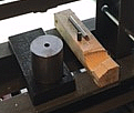
In simplest terms, once the solid fuel formula was established, the means to control forming the shape and density of the product was approached. This lead first to die and pin press to confirm initial compression testing shapes and the calorific bomb testing to confirm energy density.
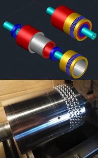
The next effort considered rolling press milling. While either die press or roller were able to form a sufficient product, the capital cost of commercial design for either Die press or Roller mill posed concerns for initial run-off testing at lower volumes.
The roller press build was shelved after testing for a longer term prospect once a larger production build should improve the viability once changes in the wood fuel material basis were through early production testing. This includes for full time, local combustion emissions testing.
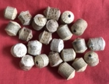
In the interim it was determined a simpler low cost, low volume approach would utilize multiple linear actuation to form the final heated material mix to a cold heading operation which dramatically simplifies the forming process with a variable design with reliable results.
As the linear actuation process remains in development at the time of this writing it is potentially under non-disclosure until working and reviewed for proprietary status. For now, the ability to form 1/4 inch (6.35 mm) through 5/16 inch (7.9 mm) shapes is a matter of hand pressing while the linear design is pending CAD design and build.
That said, we move on now to the combustion dialog. The process Carbon Analytic developed is a type of of gasifier design, but again highly unique. The gasifier is gravity fed, continuous process, open to atmosphere as a down draft chamber with hot gas take off at the bottom. Two important findings in prototype testing were discovered almost immediately.
- The size of the vertical chamber has a direct relationship with the size of the solid fuel component.
- The shape of the fuel product is essential for consistent air flow and controlled combustion.
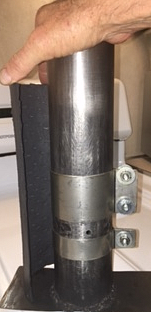
The image on the left shows the initial combustion chamber prototype from high temperature materials. Also shown is half the thermal insulator jacket which was cast from reinforced high temperature refractory material. The refractory provides thermal balance to the entire vertical stack.
The initial design allowed for atmospheric air to enter through the open top of the chamber as well as reinforcement air near the bottom, just above the high temperature zone where the fuel becomes completely or optionally consumed.
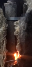
What is not shown is the hot gas take off comprised of a pipe down the center of the chamber with a specialized nozzle on the bottom where evolving hot gas is taken off to process. The nozzle sits strategically on a serviceable coupon to protect the chamber bottom from oxidizing temperature.
The image on the right shows the chamber in testing, at that time wrapped in additional protective rock wool. There were surprising results from this design right from the first effort to ignite the charge until full temperature operation was attained in less than one minute. This was due to the narrow high temperature zone near the bottom where the liberated gasses are sheared by high velocity flow induced from the lower vents where the orange glow can be seen. The lower high temperature region was surprisingly small but also emitted a sound during operation that was unmistakably similar to a jet engine combustion sound.

Fuel loading at the rate of consumption proved the combustion chamber can remain filled at all times and the consistency of the combustion process remaines completely stable and consistent. This is confirmation the thermodynamics of the fuel and process are in a controlled state. As the process air flow take off speed was varied, the flame and fuel consumption followed reliably over a relatively wide range from minimal remaining inside the exhaust plume exit to fully outside the exhaust exit on high volume.
In normal operation the gasses liberated are sent to an enclosed secondary combuster for power generation. During early testing the exhaust plume flare is used to evaluate the condition of the liberated gas.
The question remained why the sound from the combustion chamber was so distinct but also noting the color of the flame was not reminiscent of what we expected to be primarily methane.
On further testing and analysis, temperature testing in the chamber proved that we were reaching a sustained reaction temperature in the base of the chamber at around 1800 degrees Fahrenheit, (~ 1000 degrees C). We also began to notice variation on fuels which had higher or lower moisture content. The result was somewhat counterintuitive as we noticed the system produced more power with higher moisture content, something which would normally be a serious detriment to this kind of combustion. This became a critical observation in understanding the dynamic of high temperature gas flow shearing dynamics in a vacuum.
As the fuel became more carbonized during continual decomposition, its carbon content was increasing by ratio as embers of char formed. Fuel size decreased from gasification to a point where the highest temperature occurs in the base of the chamber. Under higher vacuum the radiant preheating of the fuel was releasing water vapor from the fuel above, which played into the reaction in the base of the chamber at the final reaction zone. This lead to the carbon char formation being activated to a further reaction state known as water-gas shift reaction. While the temperature in the reaction zone was already stated above, the increased and dramatic result of accelerating the gas flow across impingement points in the nozzle means the temperature of the gas molecules is reaching nearly double that temperature passing through the uptake nozzle impingement. This leads to increased conversion of flammable carbon monoxide and enriched hydrogen, further witness to the unusual color of the emitted exhaust flame confirming same. The design and material basis of the nozzle is protected from oxidation as the fuel gas at the point of impingement has become relatively oxygen depleted leaving mostly excess volatile gasses liberated to downstream.
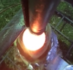
The view to the right shows a top-down view of the combustion chamber with the overhead fuel consumed such that the image shows the active combustion pile at the bottom. Much like the accidental discovery of sticky note adhesive, this output enrichment occurring was not something first intended. This was not indicative of "gasifier" process bur rather a sustained gravity fed combustion without the need of flotation bed and the emissions issues flotation causes.
It was also discovered the typical tars formed by fuel combustion were greatly reduced by the higher temperature in the lower chamber. Second, the gas takeoff is in a vertical plane from the bottom of the combustion unit. Tars which are normally problematic gather in the exit flow during vacuum dissipation, condense to a liquid which then drains by gravity back into the combustion pile as they form and the pile reaches full temperature. This is effectively a re-burning process which increases the overall residence time of the longer chain stubborn tar formations allowing them to be broken down into further flammable products. By this route, the worst of the undesirable side chain productions of solvent materials ends up being broken down to still simpler forms giving up their hydrogen and carbon providing a sustained combustion system.
By all estimates of consumption calculation this small combustion chamber trial was showing as much as 12 kWh of thermal energy conversion, almost fully transferred to the volatile gas extracted during multiple phase change reactions. The design makes the most efficient use of the fuel as it's own energy conversion resource, without consuming the greater part of the liberated gasses.
From here, the development of further amendments is both ongoing and proprietary to increase the energy density further, balance the acidic PH produced and distinguish the operating means to extract a portion of the carbonized residuals. These byproducts form an additional income stream for carbon amending depleted top soils and filtration of pesticides from irrigation water storage in farming applications. The char product also provides a secondary fuel potential as the "torrified" residuals tapped in this manner are typically similar to coal, except this form of carbon has no contribution to increased Co2 emissions. In fact, the entire process in every respect is truly carbon negative on a climate basis. What came from nature is returned to nature clean and safely repairing more than a century of negative climate and ecological complications.
In the next section under the Technology link, we examine the post treatment of gas emissions, filtration, cleaning and catalytic processes in development of the complete system before looking at the turbine power production designs and testing.
For now, progress needs for a full spectrum gas analyzer in order to make reliable changes to confirm emissions stability and identify what changes create the most beneficial result. This is a costly piece of sophisticated equipment which remains for now outside of our immediate budget. We're currently seeking a donor to assist in this need. The proof of the entire process requires the ability to demonstrate the outcome with irrefutable confirmation. The gas analyzer does this.
The next section under Technology focuses on catalytic conversion for liberated gas conditioning in preparation for final turbine combustion of the liberated gasses.


